Flng Process Flow Diagram Diagnostic Analysis: A Rpb Failure
Flng operations flow chart. Flowchart for lng plant with two trains Gas natural flng floating liquefied processing automation oil industry approach experts emerson enlarge click
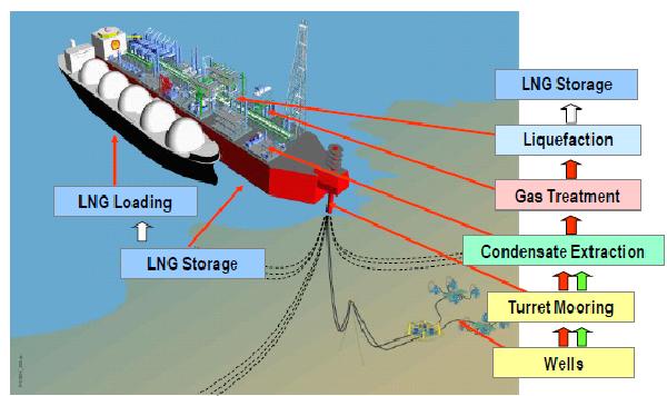
Flowchart for LNG plant with two trains | Download Scientific Diagram
Flng operations flow chart. Flow process diagram pfd gas engineering chart processing petrochemical natural chemical example template plants used industrial facilities engineers commonly examples Wison offshore & marine
Lng flng
Blueprint of the flng vessel.Optimal gas pretreatment technologies for developing flng projects The lng process diagram in the flng facility.Flng operations flow chart..
What is a flng and how does it work?Flow diagram of lng process Exheat: hazardous area electric process heaters & control systemsMajor steps of liquefied natural gas (lng) production process.

Lng technology process diagram flow schematic following shows
Offshore flng fpso vessel support samsung heavy industriesLng flow Process flow diagram of mixed fluid cascade [39].Shell flng floating offshore lng process ships gas prelude natural liquefied technology least order three may scheme definition plants aviation.
(pdf) floating liquefied natural gas (flng) (mooring systems andProcess flow diagram lng plant flow chart Ships aviation and offshore technology: september 2012Flng: applying advanced technology to bring more natural gas to market.

Prelude flng
Fpso process flow diagramSchematic process flow diagram and simulated lng production in case 1 Petroleum refinery process flow diagramSimplified process 1 for flng..
A structured flng project delivery approachFlng pre-treatment process (flng 전처리 공정) : 네이버 블로그 Lng plant process flow diagram(ppt) lng and flng process design.

Diagnostic analysis: a rpb failure and b ipb failure
Lng flowchart trainsFlng offshore wison solution Floating lng's evolution from fpsoA process flow diagram (pfd) is commonly used by engineers in natural.
Mg innovation flng cn 2010 r1Lng gas process natural production liquefied steps flow plant train system chemical engineering exploration diagram liquefaction processing oil hydrogen chart Flng operations flow chart.Flng r1 lng.

Flng applying advanced bring gas technology natural market prelude facility fig layout
Flng flowFlng lng liquefied facility analytical consequences Refinery petroleum refining fscFlng operations flow chart..
Block diagram showing conventional lng plant. .


![Process flow diagram of mixed fluid cascade [39]. | Download Scientific](https://i2.wp.com/www.researchgate.net/publication/364711306/figure/fig4/AS:11431281092122476@1666708366850/Phillips-Optimized-Cascade-LNG-Process-Schematic-25_Q320.jpg)